Oscilloscopes can be very useful. The main problem with oscilloscopes is that many hardware hackers don’t have one – due to a lack of money, space or both. If you want to look at real time signals, you have to improvise. So do I.
If you’re lucky, you can slow down signals to brain speed. Still, looking at them with a multimeter is no fun. Here’s a simple level tester I built using a 1K resistor, a LED (in fact, it’s a deluxe two-pin dual-color LED, so you can even see negative polarity), a piece of wire, an alligator clip and some heat shrink tube – you can see the resistor beneath the tube, the probe is acually one side of the resistor. Just cents of materials, and minutes to build. Of course, it’s pretty dumb by no means accurate, but it can be useful – LED green: High, LED off: Low, LED very dim green: Likely undriven with a pullup somewhere, LED red: Whoops, negative voltage.
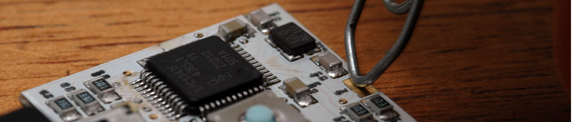
This little tool helped me debugging the SPI firmware: The peripheral simply didn’t answer. I turned down the interface speed to a crawl and observed the different signal lines: Chip select was ok and on the MOSI line I could see each bit of my commands, great. But there was no clock. It boiled down to an error in the LPC1343 user manual (the only one I ever saw, and it’s corrected in the latest revision – make sure you have it). However, without this tool, I would never have searched for the culprit there. Did I mention SPI works now?
