Everykey was on then road again… We had a small appearance at the wonderful Raspberry Pi Jam hosted by Ordina in Utrecht (NL). The event seemed almost like an embedded hardware jam, with talks by the folks from the Amersfoort Hackspace Bitlair (the guys responsible for the awesome LED lighting at OHM2013 — roughly 1 km of RGB LED strips turned into remote controllable “streetlights”), Gert van Loo, one of the engineers responsible for the Raspberry Pi board and maker of the Gertboard expansion. Finally, Jeremy from Autostatic demonstrated real time audio effects. Only problem was that I was too busy talking to people (and regretting not speaking Dutch) that I forgot to take pictures! Thanks to Ordina for this event and especially to Marco Hebing (@TRexX) for inviting us!
Category Archives: Hardware
The Real Kicker! (Electronic Foosball)
We know you’ve always dreamed of having an electronic foosball table that saves you the tedium of counting and has the added advantage of shooting sparks when you spill beer on it! We started construction with friends at Railslove, got things nearly done at Interactive Cologne and finally finished what we started at the Pirate Hack in Cologne.

The foosball table even has it’s own website. It features automatic goal detection and can even calculate the speed of the ball. It’s got two displays to inform you about the current score. It’s also got Wifi (and an App in the “cloud“!), freeing you from the tedium of having to keep track of your league. It also has buttons that you can press!
Oh, and did we mention that it comes with it’s own lamp that can change the lighting conditions automatically corresponding to game play.
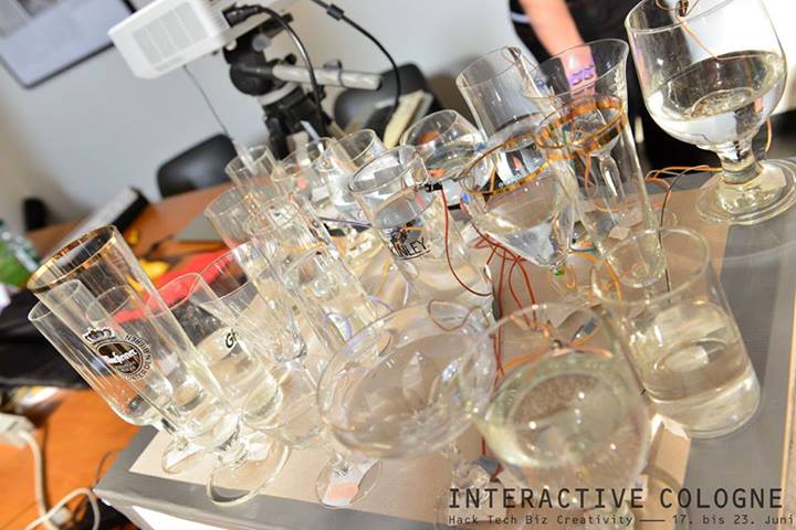
Everykey at Interactive Cologne

Just so you know:
we will be presenting rev2 of the Everykey at Interactive Cologne on June 18th and 19th in Cologne. We’ll be around building an interactive musical instrument based on Everykey together with visitors. Say, write or tweet something nice about us, let us know and you can win a free ticket to this awesome two day event! (it’s a hackathon and startup conference rolled into one…)
Quick Update!
Here’s what we built:
New Member of the Everykey Family
Oh the perils of unattended technology! We left two Everykeys alone for a couple of minutes (max!) and look what happend:
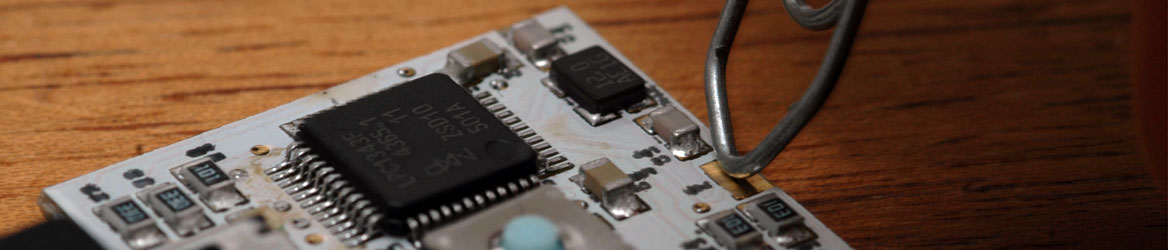
We’re happy to announce that we just picked up the first batch of a new revision of the PCB, assembled some keys and … everything seems to work nicely!

Features
- Two buttons! (Both RESET and PROGRAMMING mode pins on buttons, no more re-plugging)
- 30% Smaller: svelte 20×20 mm instead of bovine 24×24 mm
- 0603 component size (“Do these 0805 resistors make my ass look fat?”)
- Large top layer pads and additional diodes to allow easy, safe connection of external power and access to USB voltage
- Readable print on the PCB!
- Of course, we kept all breakout pads on the back side (ribbon cable pitch)
As things seem to work, we’re now getting ready to release the schematics and board files, updating the site and SDK.
If you want to see our baby up close, why not drop by Interactive Cologne? (We’ll provide an update about other upcoming conferences and appearances soon…)
A trip to the 80s
I recently found a rare 80’s technology gem on the attic: An (almost) functional Commodore 1520 plotter. This was the only plotter ever sold by Commodore. It was a C64 peripheral, although even back then, it was pretty unknown (and fairly useless).
Surprisingly, after 25 years of deep sleep, the device powered up to self test. Two motor gears needed some glue and the ink in the pens had dried. A bit of water brought at least the blue pen back to life (the plotter has four pens in different colors, for a “perfect multimedia experience”).
Commodore, like just about everyone else back then, used a propietary protocol to drive the plotter. It is a weird serial protocol – in our official Everykey protocol weirdness scale, it beats most other protocols by far, making I2C and SPI look boring and straightforward. There’s even some (partially incorrect) documentation on the web. And you can still buy the 6-pin DIN plugs. There are some projects to control the Commodore 1541 floppy disk drive, but we didn’t find any good approaches on bringing the 1520 back to life. Challenge accepted!
The implementation was surprisingly simple – after categorizing the existing documentation into a) usable, b) incomplete or c) just plain wrong. The Everykey connects through USB to a computer and shows up as a virtual serial port. It implements a tiny parser which interprets simple commands (such as MOVE, LINE, PRINT or COLOR) typed into the terminal and translates them into something that can be understood by the plotter. Here’s an early result (just blue – as mentioned, the other pens are still dry):

The output quality is not perfect (for example, you can see that the vertical feed is off a little), cleaning the mechanics and replacing the pens should help. Even in perfect condition, the results could not compete even with the cheapest inkjet printer of today. So why did we do it? Because we can.
Code and schematics are not online yet since we decided to stop spamming our base repository. If you’re interested in how it works, let me know. If you have other peripherals waiting for resurrection, we might be able to help – did you know that we are for hire for this sort of stuff?
There’s a video of the plotter in action on youtube.
CNC Progress…
We’re very excited about our new toy here at Everykey World Headquarters. We ordered an el-cheapo brand CNC router that we’re hoping to use to make cases for the Everykey and PCBs for new prototypes. While buying cheap hardware in China has some advantages (such as apparently including an AutoCAD license for free on the CD…), there are some drawbacks to consider:
- You’re obviously not going to be sure of the quality you’ll be getting. One generally prefers a solid and stable machine milling parts in sub-millimeter accuracy. So far, we’re impressed by the mechanical robustness. Everthing seems robust and was layed out quite “pragmatically” which served well to make the machine hackable. The included spindle, while usable, was the only part that we’ve had any concerns about mechanical quality – there’s too much backlash for accurate, even surfaces (however, results are still much better than 3D prints). Fortunately, the spindle turns out to be a Foredom H.30 handpiece ripoff with US standard flex shaft attachment, so it should be fairly simple to replace.
- The “english language” manual starts off with this reassuring gem: “Responding to be installed in the gas containing the explosive environment, otherwise have caused the explosive danger”
- The CNC controller only has a parallel port and we don’t have any computers from before 2000 laying around that have a suitable connection.
Opening the controller box reveals its quite shocking circuitry: It mainly consists of one Allegro A3977-based stepper driver board per axis, properly done with insulated inputs via optocouplers. That’s the good news (the A3977 is a very nice chip and optocouplers are a good thing to have if you’re going from logic levels to higher power domains). The bad news is that there’s another board between the parallel port and the stepper drivers, containing a line driver. It’s probably there to boost (some of) the parallel port signals to a level that can reliably drive the optocouplers. Unfortunately, this board is powered by the controller, nullifying the galvanic insulation and therefore rendering the optocouplers quite useless. We’ll address that later – for now, we will use it as is, very carefully.
Off-the-shelf USB-to-Parallel adapters don’t work for controlling CNC mills: The parallel port pins send step signals directly to the stepper controllers. For usable speeds, you need precisely timed signals with 10 KHz or more. That’s too much for ordinary converters because of the fixed 1 KHz framing of USB (these high frequencies are even a challenge for PCs, so CNC CAM applications usually need to use tricks to make it work, i.e. make use of low level timers for driving the parallel port).
Hence, in order to talk to our CNC mill, we had to do something. Fortunately, we had some Everykeys and line drivers laying around to solve that problem (the purpose of the 74HCT244 line drivers is to shift the voltage levels from our 3.3V to 5V found at parallel ports). We have two options: a) Talk directly to the stepper driver boards or b) talk to the parallel port. For now, we decided to take the second option as it would also work for other CNC machines without modification, despite the “interesting” circuit mentioned above. Later on, we might replace that part with our solution to provide both USB connectivity and electrical safety (our line drivers can deliver enough current for the optocouplers, so the board is not needed any longer). This will also enable us to make use of the fourth axis which came with the machine: There are four stepper drivers, but the fourth axis is controlled by parallel port pins that cannot be driven easily by PCs.
The host does not control the steppers directly, but sends higher level motion commands to the Everykey, which takes care of stepper controlling and reporting the CNC mill state back to the host. Right now, we’re running at 20KHz, but there seems to be plenty of headroom for more.

Within a week, we were self-hosting. Here’s a picture of the elegant casing we made for our USB to Parallel Port adapter:

… as well as some shiny, acrylic glass Everycases:

Currently, we’re controlling the device via USB HID, which is working out quite nicely. We’re still using a roll-your-own scripting language, but are hoping to be able to import G-Code soon at the very least.
For the truely painless, there’s some code available for perusal in a secret hidden branch under the `examples` directory of the SDK. The host side of the project is still in such a pre-alpha stage that even we’re ashamed to release it. We’re working on controller software in Objective-C/Cocoa and node.js, fairly obvious plattform choices for interfacing to hardware 🙂
No oscilloscope?
Oscilloscopes can be very useful. The main problem with oscilloscopes is that many hardware hackers don’t have one – due to a lack of money, space or both. If you want to look at real time signals, you have to improvise. So do I.
If you’re lucky, you can slow down signals to brain speed. Still, looking at them with a multimeter is no fun. Here’s a simple level tester I built using a 1K resistor, a LED (in fact, it’s a deluxe two-pin dual-color LED, so you can even see negative polarity), a piece of wire, an alligator clip and some heat shrink tube – you can see the resistor beneath the tube, the probe is acually one side of the resistor. Just cents of materials, and minutes to build. Of course, it’s pretty dumb by no means accurate, but it can be useful – LED green: High, LED off: Low, LED very dim green: Likely undriven with a pullup somewhere, LED red: Whoops, negative voltage.
This little tool helped me debugging the SPI firmware: The peripheral simply didn’t answer. I turned down the interface speed to a crawl and observed the different signal lines: Chip select was ok and on the MOSI line I could see each bit of my commands, great. But there was no clock. It boiled down to an error in the LPC1343 user manual (the only one I ever saw, and it’s corrected in the latest revision – make sure you have it). However, without this tool, I would never have searched for the culprit there. Did I mention SPI works now?
